

The BITX40 is shipped as a set of two boards : The Raduino and the Main Transceiver Board, with connectors and external components. You have to supply your own cabinet, mic, speaker, power supply and Antenna. Soldering is required, but all of the SMD and other components on the Main Transceiver Board and already soldered in place for you. Your kit-building efforts are little more than connecting the off-board controls via the supplied wiring connectors.
The Raduino The new BITX40’s Raduino is a small, hackable, board utilizing an Arduino Nano to control a rock-steady Si5351 synthesizer and a clean 16×2 frequency display. The program code is free and Open Source. The Raduino features 6 analog ports, three oscillators and six digital lines.
Receiver Listen to the very clean, crisp, and quite receiver. The front-end has a triple-tuned circuit that limits out-of-band signals. The diode ring mixer front-end makes this a crisp receiver that doesn’t overload easily. The all-analog signal path to your ear provides outstanding signal clarity that must be heard to be believed.
Transmitter 7 watts of low distortion SSB provides you with enough power to have thousands of contacts on 40 meters, daily rag chews, and occasional DX chasing. Any common 2 ampere, 12 linear volts, power supply will provide enough juice for this transceiver. Or you could simply run it from a battery!
Click for more infos about Bitx40
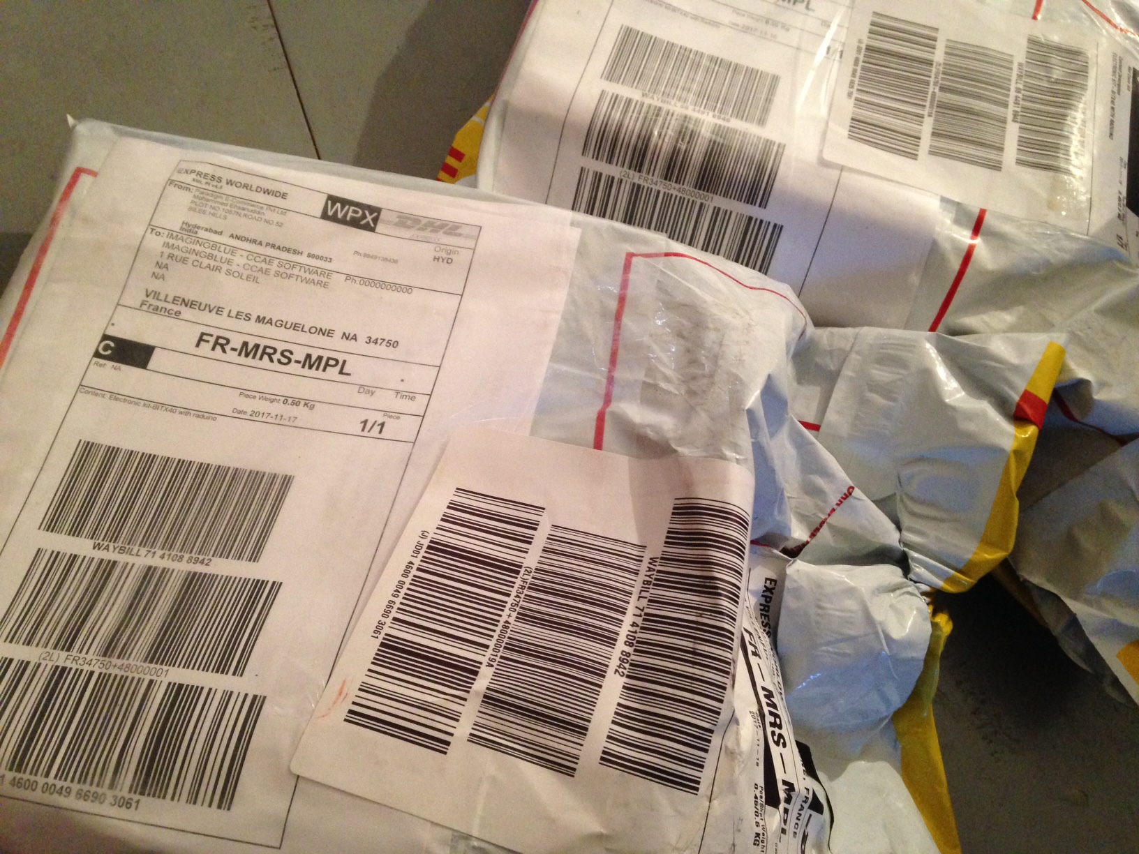
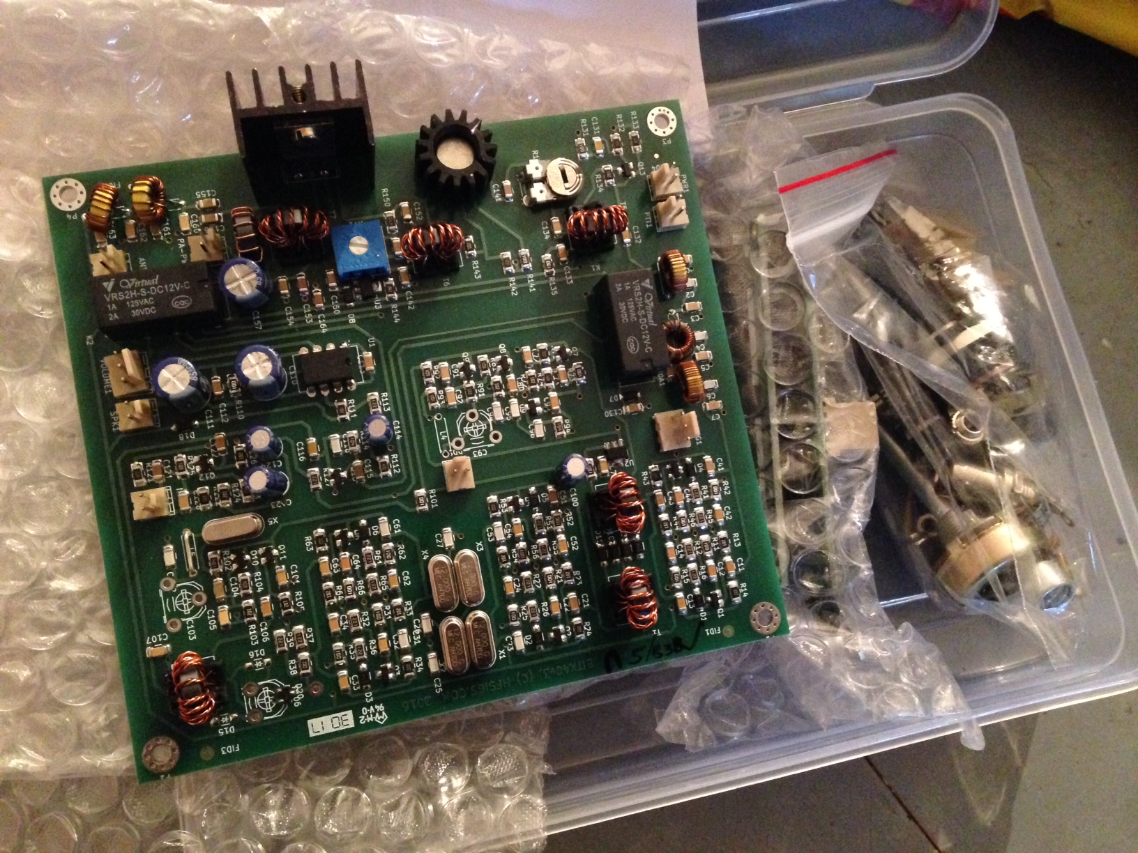
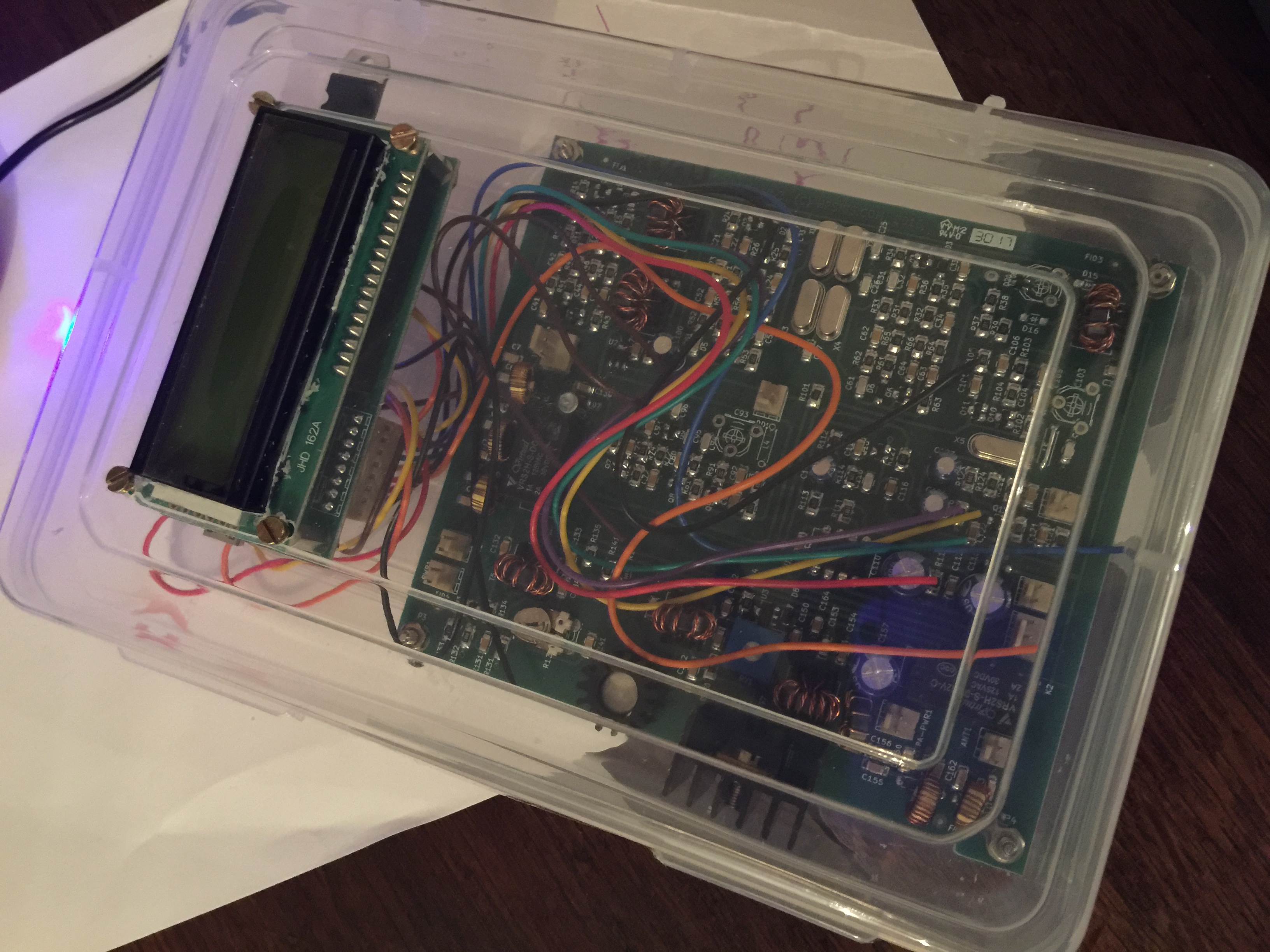
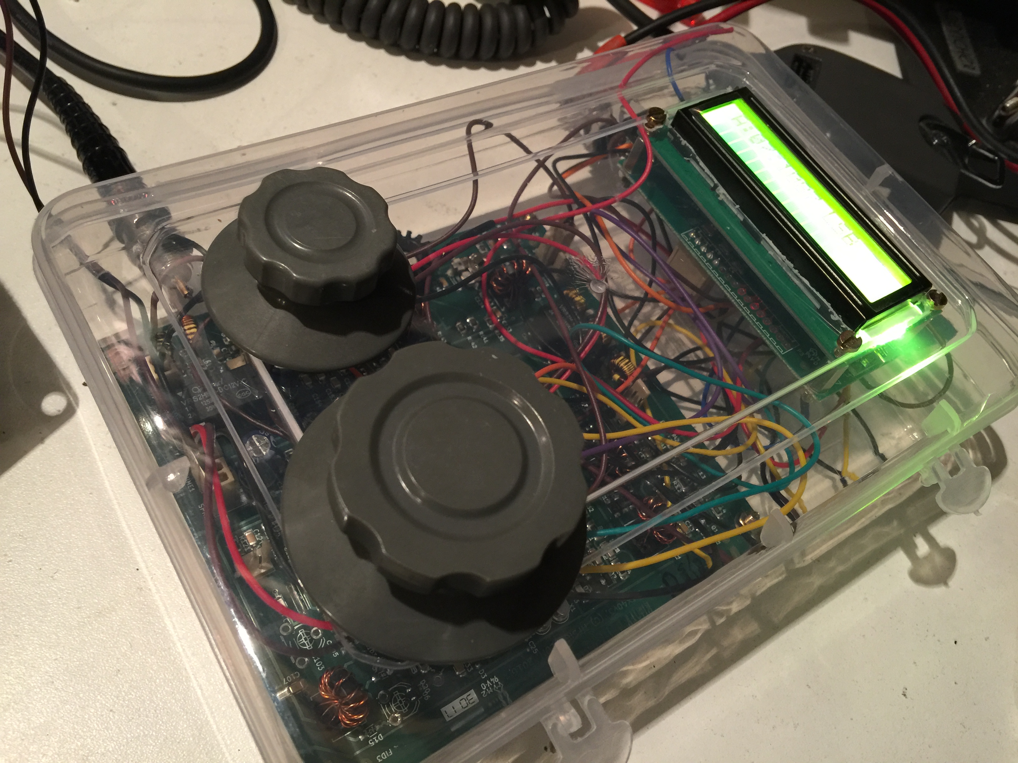 First tests in the packaging box…
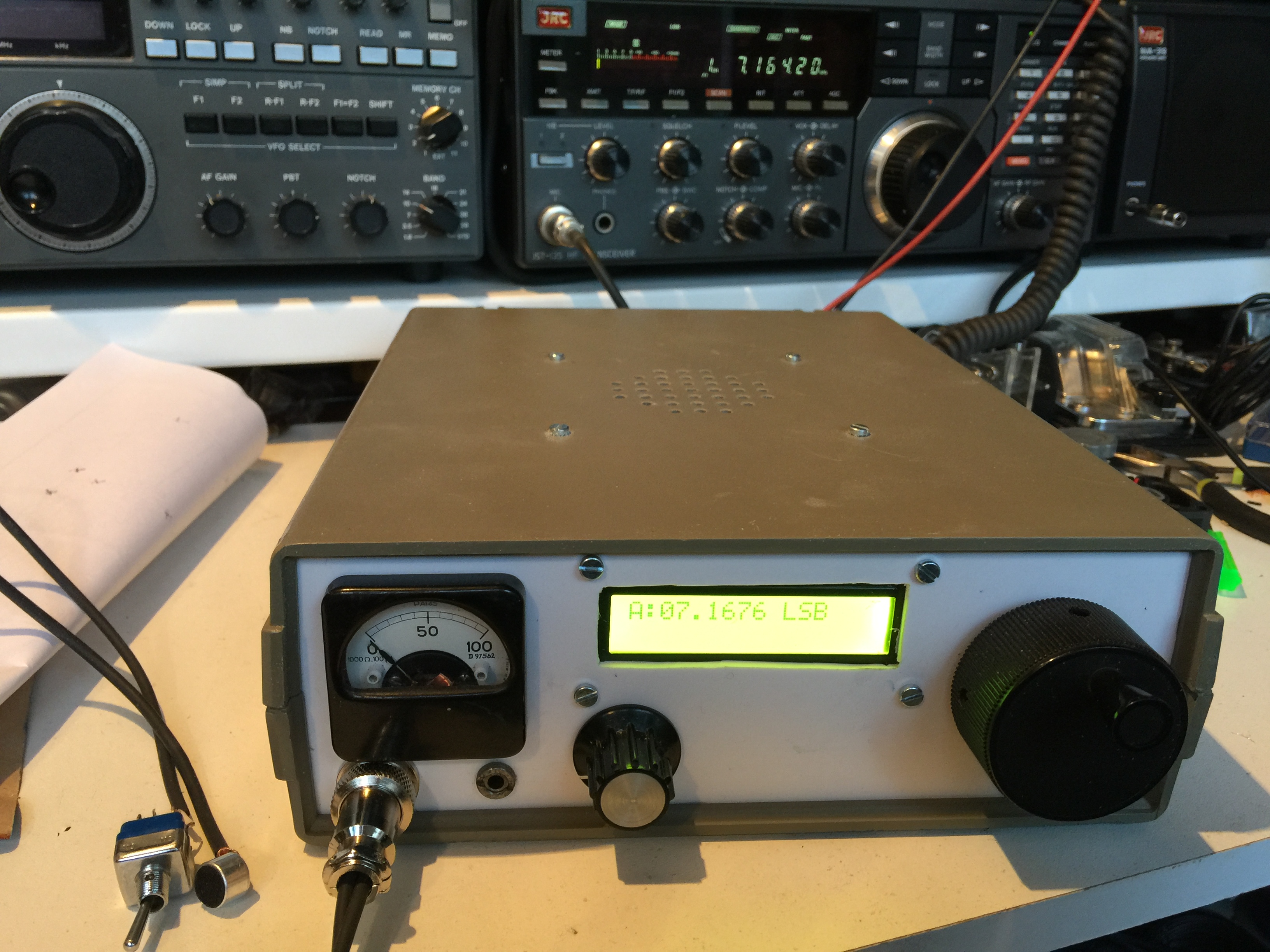
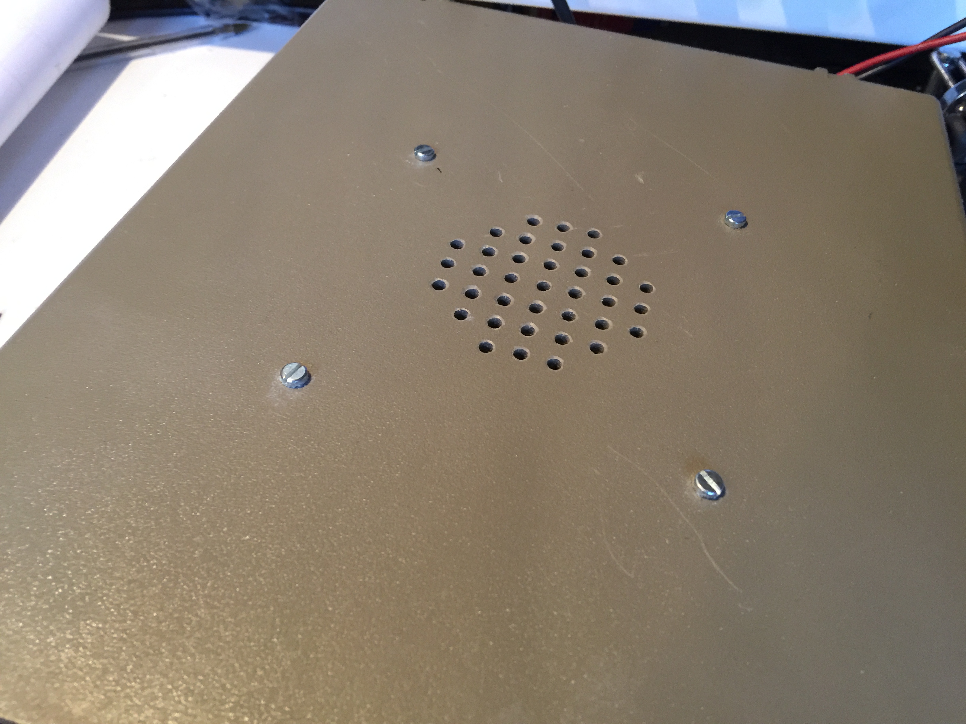
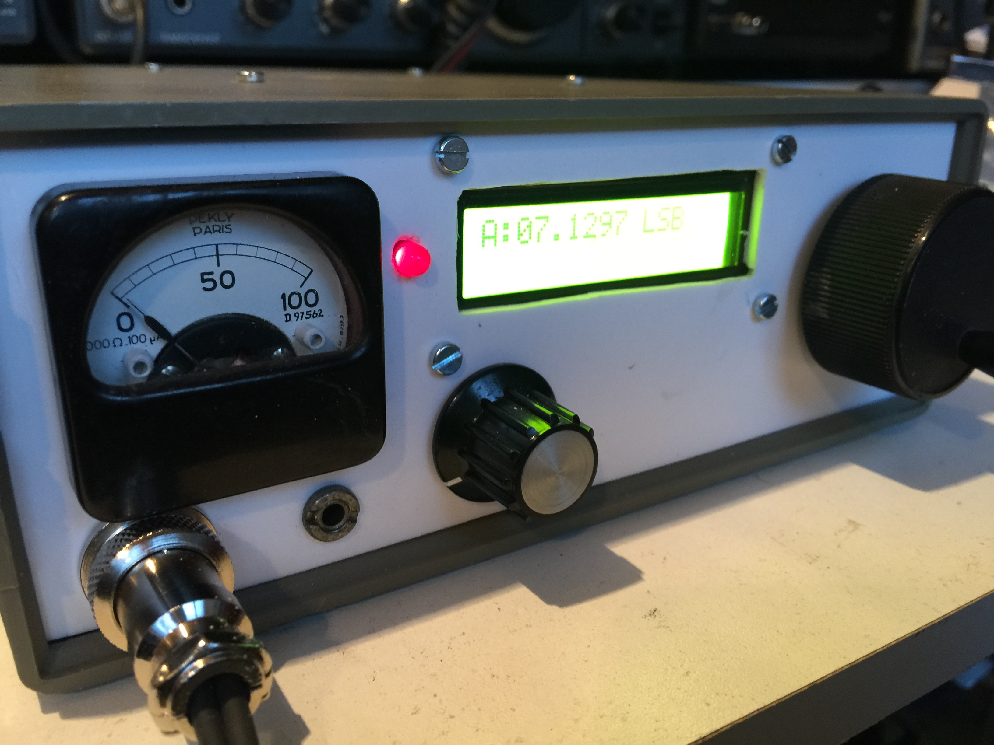
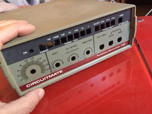 Find a box (thanks F6GUN)
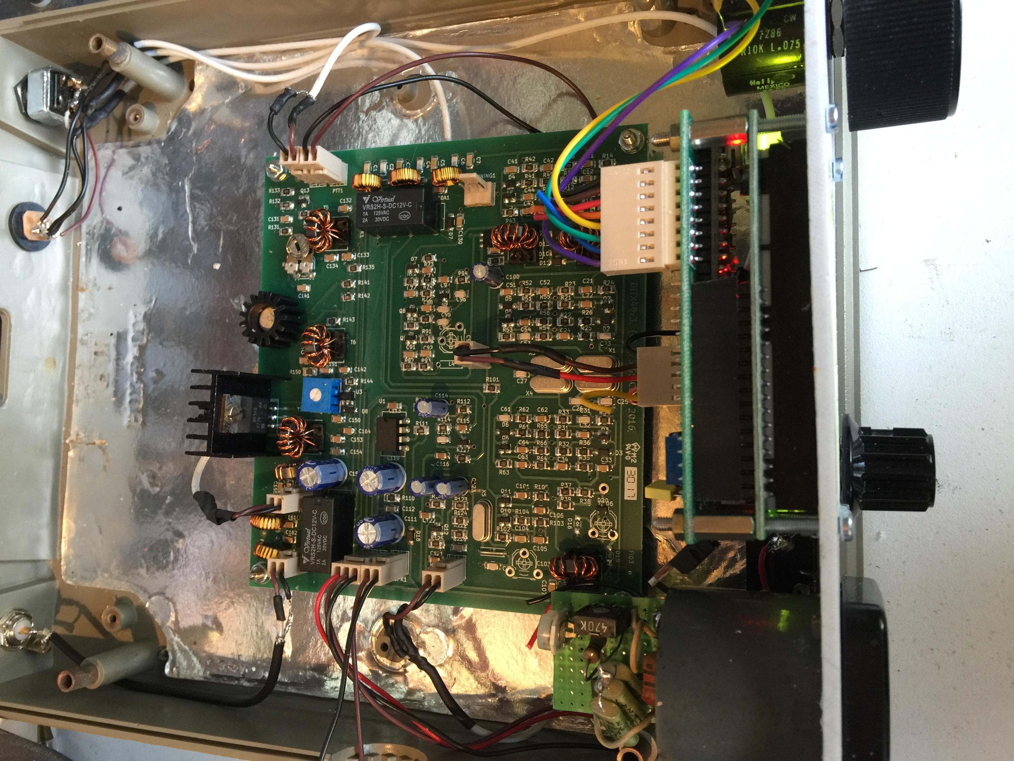
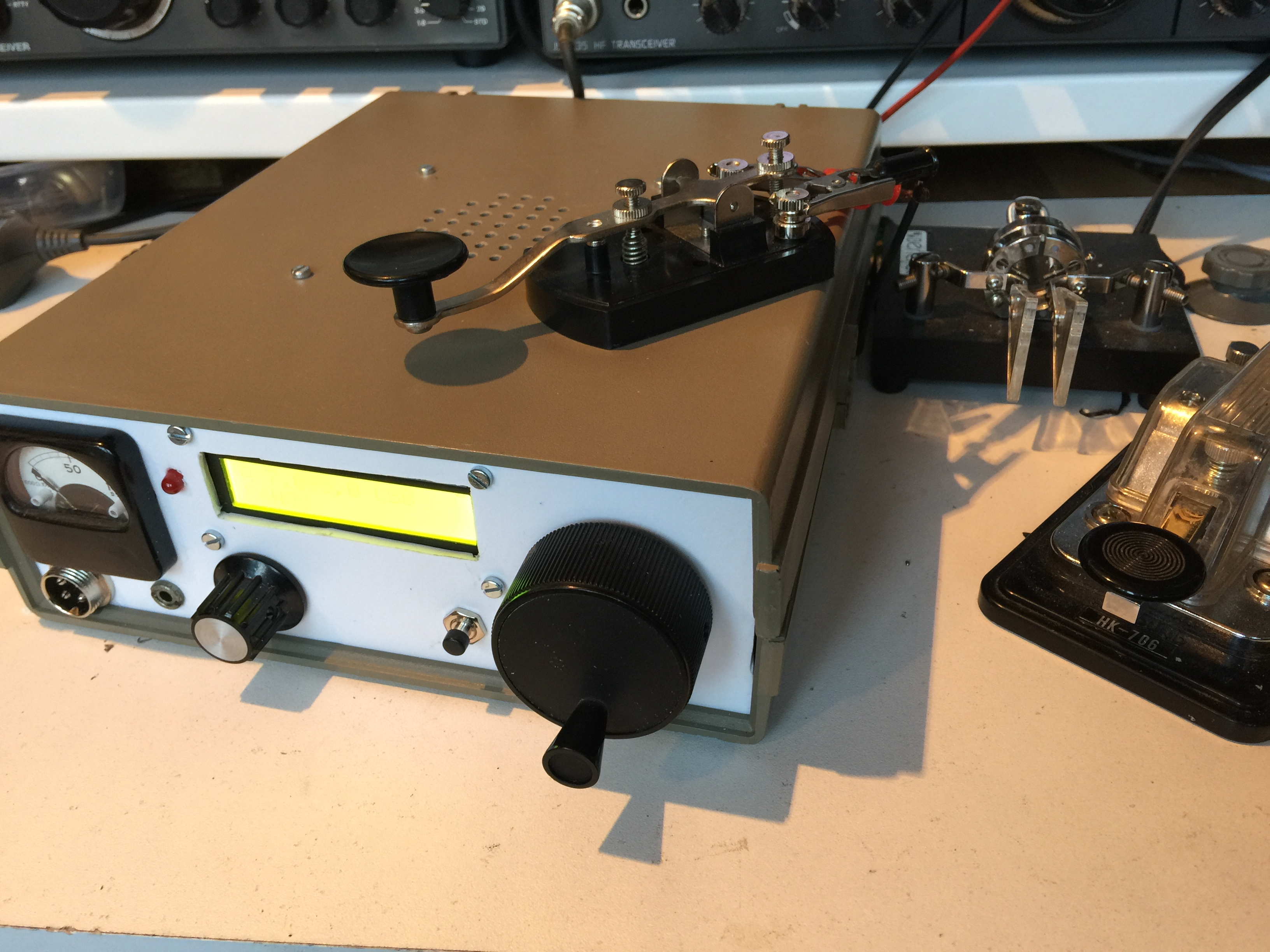
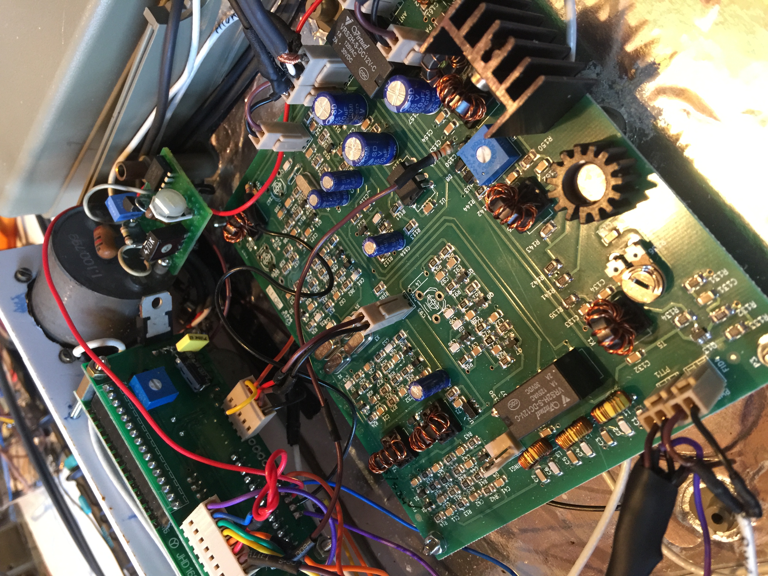
I add S meter, change the pot by a multitour 100K, and a nice wiring with teflon.
Wiring with Teflon and shielded wire to prevents noise from the DDS.
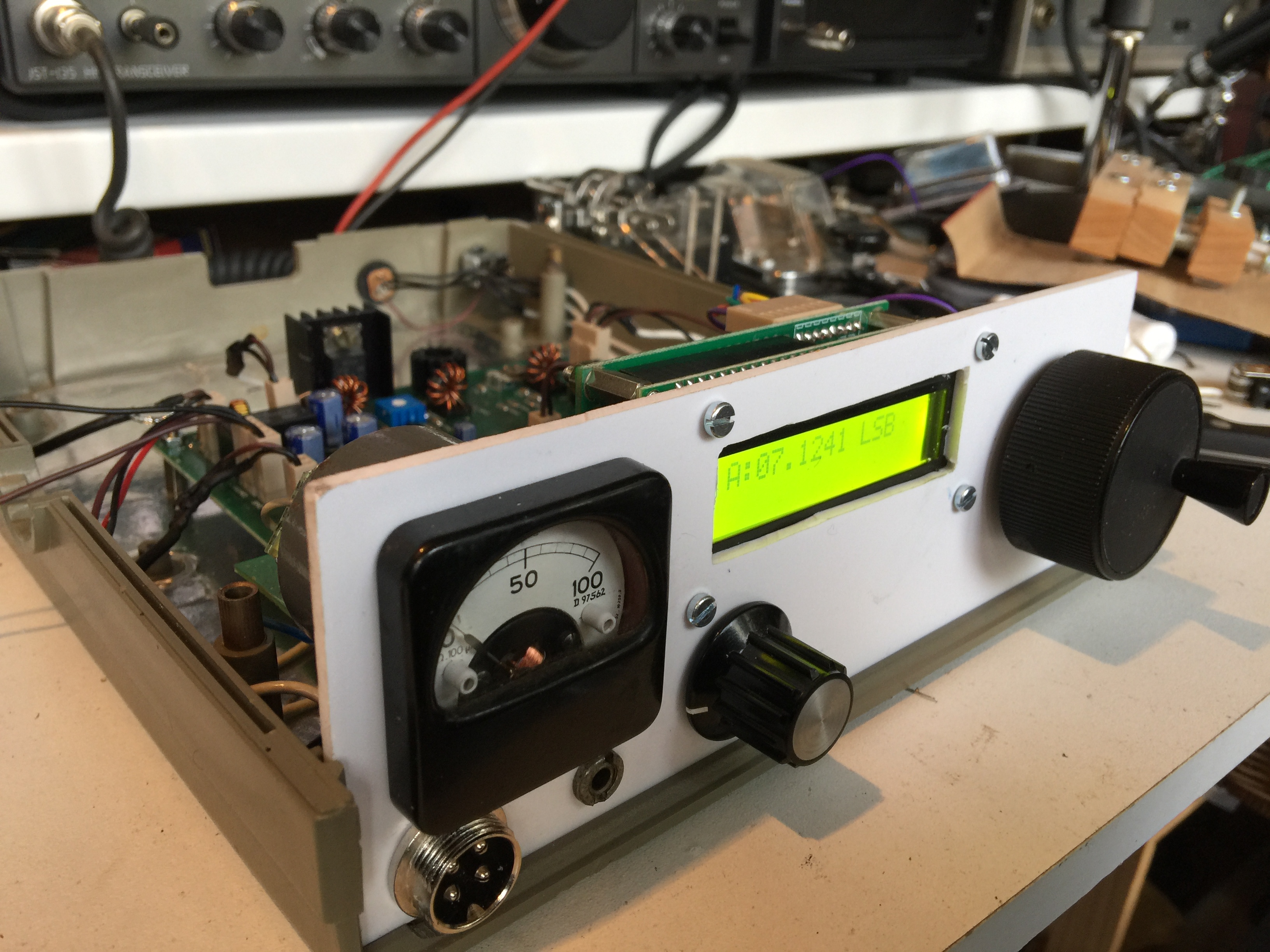
S’meter
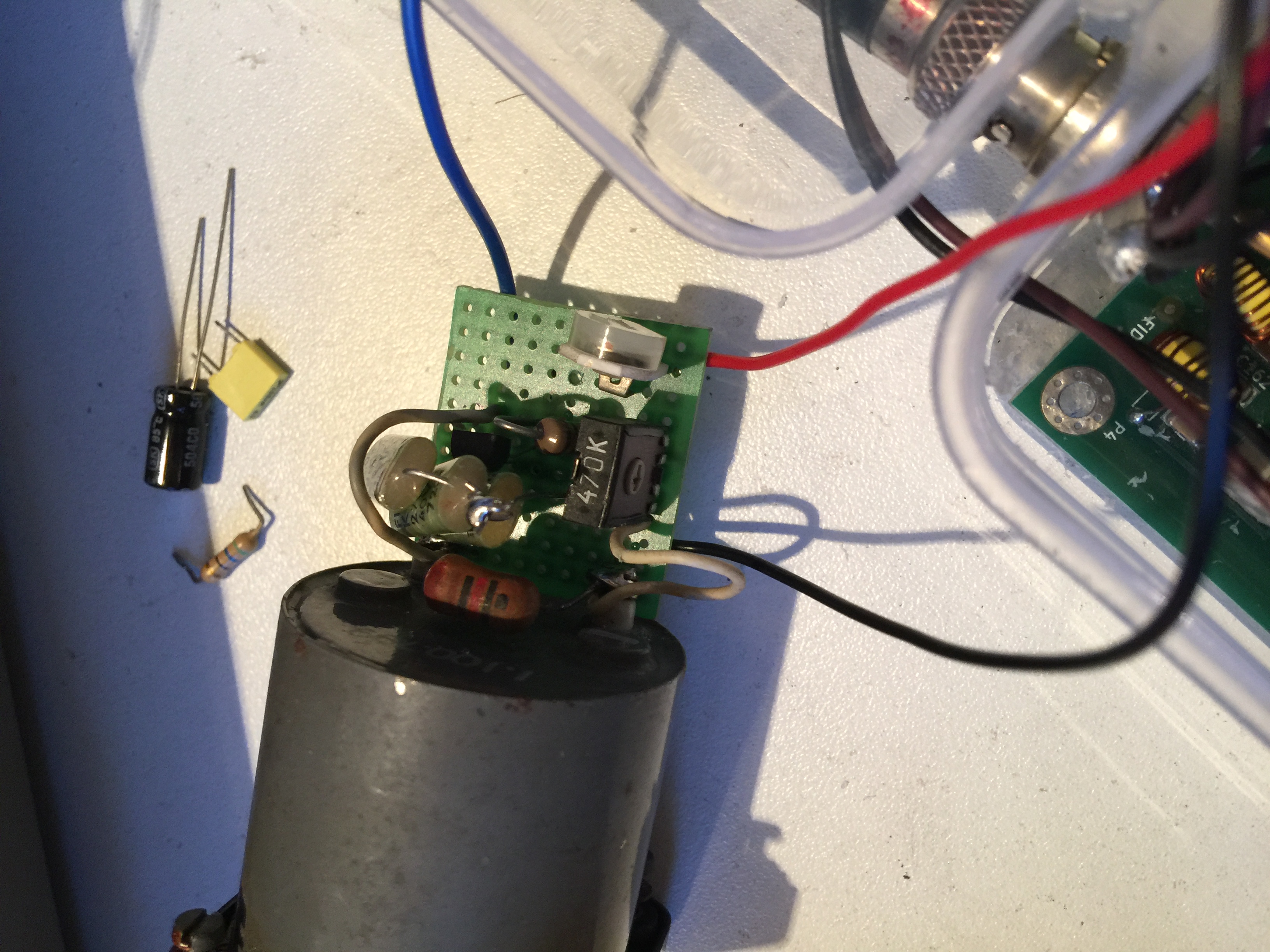
I found several ideas on the net for a s’meter.
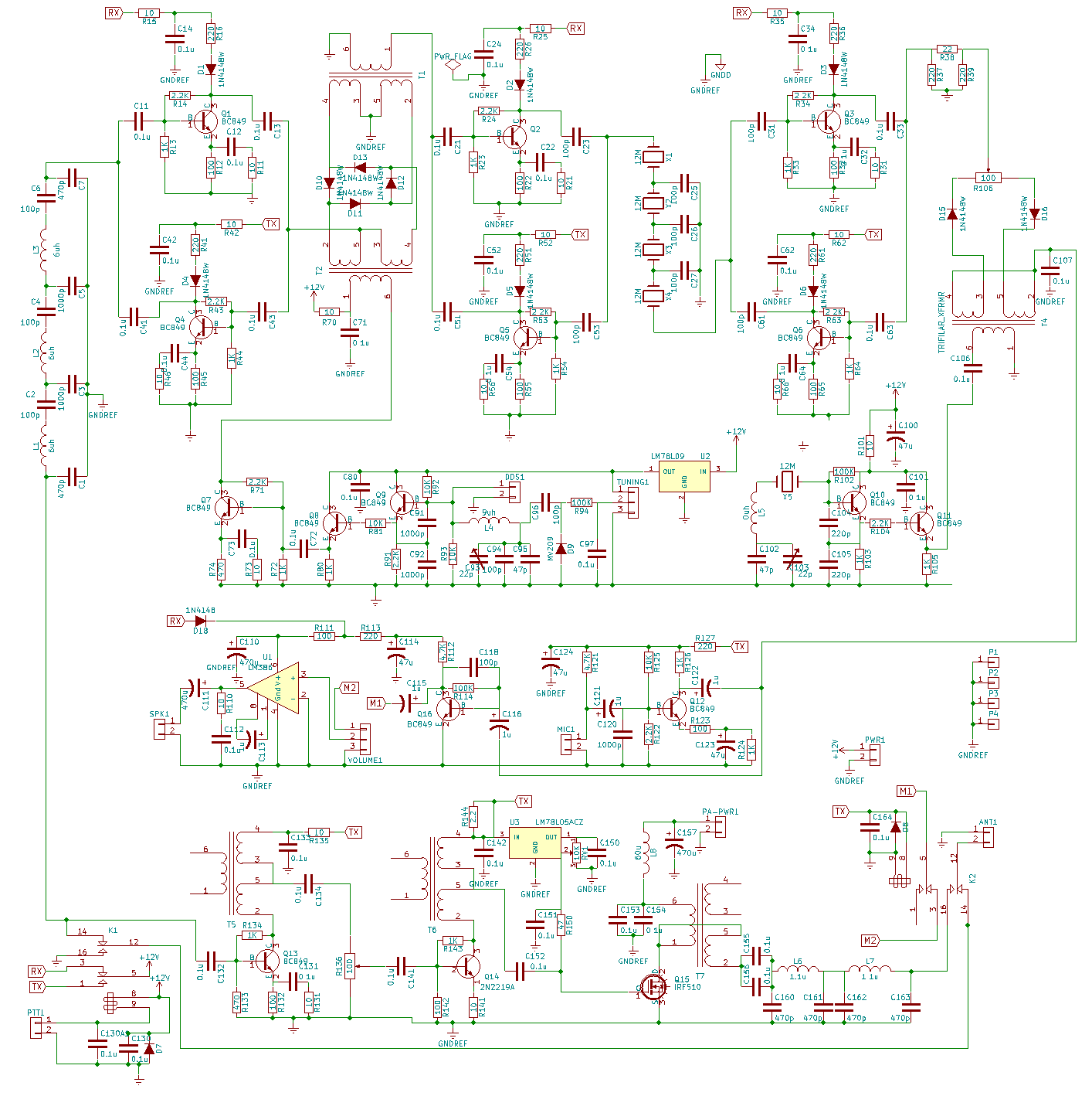
I was inspired by the s’meter of F6BQU for his small fForty Transceiver. This is what i have done:
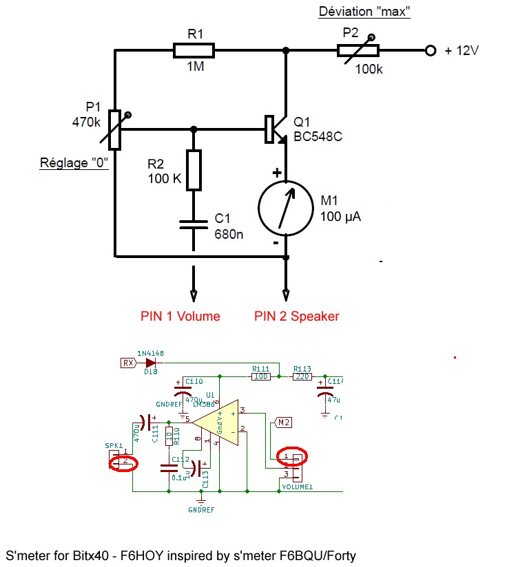 Do not try to connect to ground.
Only on pin 2 of the speaker.
Yes it is not a real s’meter. It is just an audio level meter but it is fine in my case.
As there is not AGC you have to adjust a good audio level for your ears on a strong signal and adjust P2 and P1.
For a signal of about 59 the meter indicates 50%.

another idea similar found on the net
 A small red led during transmission. 12V on pin 1 of K1 relay.
User instructions for Raduino_v1.27
https://github.com/amunters/bitx40
IMPORTANT: This sketch version requires the library « PinChangeInterrupt » for interrupt handling. Use your IDE to install it before compiling this sketch.
After a version update all calibration data, drive level settings, etc will be reset to ‘factory’ values. Before updating note down your cal values etc. After the update use the Function Button to set them back again. Without any hardware modifications the sketch provides basic LSB functionality. Depending on the user’s choice, additional functionality provided by this software can be activated by installing the related (minimal) hardware mods. See the table below showing which mods are required for each function. Details of each mod are described below.

10-TURN TUNING POT
The default frequency span of the standard supplied 1-turn tuning pot is only 50 kHz. If you install a 10-turn pot instead you can extend the span for full 40m band coverage.

Using the Function Button, go to the SETTINGS menu and set the desired pot span.
FUNCTION BUTTON WIRING:
Connect a momentary pushbutton between pin A3 (connector P1, orange wire) and ground. Arduino’s internal pull-up resistors are used, therefore do NOT install an external pull-up resistor!
Don’t have a Function Button (yet)? If you don’t install a pushbutton then the basic LSB functions will still work. (of course you will miss the dual VFO, RIT, SPLIT, USB, CW, etc. then). Calibration can still be done in the old fashioned way by using the CAL button (connector P1, pin A2 – red wire). The tuning range setting can be ‘hard coded’ by editing lines 34-36 and adapting the values to your needs. After recompiling and uploading to your Raduino, momentarily switch the red CAL wire to ground to initialize the new settings.
PIN LAYOUT

Connector P1 (8 pin)
- A0 (black): PTTSense
- A1 (brown): Key, « dit »
- A2 (red): CAL
- A3 (orange): Function Button
- GND (yellow)
- +5V (green)
- A6 (blue): unused
- A7 (purple): Tuning Pot
Connector P3 (16 pin)
The first 11 pins have no headers (pads only):
- D7: TX-RX
- D6: CW Carrier
- D5: CW Side Tone
- D4: CW SPOT Button
- D3: Key, « dah »
- ??: Unused
- ??: Unused
- ??: Unused
- ??: Unused
- ??: Unused
- ??: Unused
The 5 pin header
- GND (black)
- GND (brown)
- CLK2 (red)
- +5V (orange)
- ?? (yellow): Unused
PTT SENSE WIRING:
Connect pin A0 (connector P1, black wire) via a 10K resistor to the output of U3 (LM7805 regulator) on the BITX40 board.

When the PTT is not pressed (RX mode), the regulator will be off, so pin A0 will see 0V (LOW). When the PTT is pressed (TX mode), the regulator will be on, so pin A0 will see +5V (HIGH). The PTT SENSE is required for the CW, RIT, SPLIT functionality, and for disabling frequency updating during TX (to prevent « FM-ing »). If you don’t install the PTT sense, LSB and USB operation will still work normally.
CONNECTING A STRAIGHT MORSE KEY or ‘TUNE’ BUTTON:
A straight key (or external electronic keyer) can be connected to Raduino pin A1 (connector P1, brown wire). It is recommended to install a 1K series resistor to protect the Arduino input. When the key is up (open) pin A1 will be HIGH. When the key is down (closed, shorted to ground) pin A1 will be LOW, and a carrier will be transmitted.
You could also wire up a simple push button instead of connecting a morse key. The generated CW carrier can be used for tuning up your antenna. In that case please note that you will be transmitting a carrier at full duty cycle, therefore don’t keep the tune button pressed for too long to prevent overheating the final!
AUTOMATIC KEYER – CONNECTING A PADDLE:
The Raduino is set up for straight key operation by default. If you want to use the automatic keyer, go to the SETTINGS menu and to ‘CW parameters’ => ‘Key-type’ and select ‘paddle’, ‘rev. paddle’ (for left-handed operators), ‘bug’, or ‘rev. bug’. Connect the ‘dit’ contact to Raduino pin A1 (connector P1, brown wire). Connect the ‘dah’ contact to Raduino pin D3 (connector P3). It is recommended to install 1K series resistors to protect the Arduino inputs. The built-in keyer provides Iambic mode A and ‘bug’-mode (Vibroplex emulation) functionality and the paddles can be reversed.
CAPACITIVE TOUCH KEYER:
The sketch supports Capacitive Touch functionality. With this feature it is possible to use touch sensors instead of a mechanical morse key or paddle. Manual straight key as well as automatic keyer operation is possible via the touch sensors. See the following demo: https://www.youtube.com/watch?v=9MWM6UVy9k4
A minimal modification (add four resistors) is required for this function. Note: some builders reported that the touch sensor wasn’t reliably detected during power on, in that case add some small (3-22pF) capacitors to both inputs in order to slightly increase the internal ‘base’ capacitance.

The capacitive touch sensors are disabled by default. To enable them, go to the SETTINGS menu and to ‘CW parameters’ => ‘Touch sensor’, and use the tuning knob to set the desired touch sensor sensitivity.
A good sensitivity value to start with is 22. Increase the value for more sensitivity. The maximum value is 25. The sensitivity setting is quite delicate and depends on your personal taste. The best results are usually obtained with high sensitivity. However, if the sensitivity is too high, the radio may be keyed by electrical noise or objects nearby the touch pads. It may also happen that iambic keying will occur even when only one touch pad is touched. Reduce the sensitivity if these symptons occur. On the other hand, if the sensitivity is too low, the keyer may not respond properly to the touch pads, for example double DITs or DAHs may be generated. Some experimentation may be required to find the optimum setting.
The touch sensors are calibrated automatically at start up. If you want to recalibrate them, simply power OFF and ON again, while NOT touching the sensor pads. The sensor calibration data will be shown on the LCD display at start up. Note: When the touch keyer is enabled, normal paddle operation is not possible. If you want to use a standard paddle, disable the touch sensors by setting the sensitivity to 0 (touch sensor OFF).
CW-CARRIER WIRING:
This is required for CW operation (or when you want to generate a carrier for tuning) Connect a wire from Raduino ouput D6 (connector P3, pin 15), via a 4.7K series resistor, to the input of the mixer.

When the key is down ouput D6 will be HIGH. This injects some DC current into the mixer so that it becomes unbalanced. As a result a CW carrier will be generated.
Note: If the carrier is not generated at full output power, you may need to reduce the 4.7K series resistor to a lower value for more drive. However try to keep it as high as possible to keep a clean CW signal. Never use a resistor less than 1K! Extra tip: For tuning purposes a reduced carrier is usually desired. You can optionally connect a 100K pot in series with the 4.7K resistor, this will allow you to reduce the strength of the carrier to a suitable level.
The CW-CARRIER is only required for CW functionality. If you don’t install this line everything else will still work normally.
CW SIDE TONE WIRING:
A side tone is available at Raduino output D5 (connector P3, pin 14). This signal can be fed to the speaker/headphones in parallel to the output from the existing audio amplifier.

The desired side tone pitch can be set using the Function Button in the SETTINGS menu. The CW-side tone is only used for CW operation. If you don’t install this line everything else will still work normally.
TX-RX WIRING:

This is required for CW operation.
When the key is down output D7 (connector P3, pin 15) will be HIGH. It will only go LOW again when the key has been up for at least 350 ms (this timeout value can be changed via the SETTINGS menu). This signal is used to drive an NPN transistor which is connected in parallel to the existing PTT switch, so that it will bypass the PTT switch during CW operation. As as result the relays will be activated as long as D7 is HIGH. (Suggestion: If you have a combined microphone/PTT connector, the PTT bypass transistor can be soldered directly on the back of it). (The PTT bypass transistor may be used in the future for VOX functionality as well).
CW SPOT/FINE TUNE Button:
Connect a momentary pushbutton between pin D4 (connector P3) and ground. Arduino’s internal pull-up resistors are used, therefore do NOT install an external pull-up resistor! When operating CW it is important that both stations transmit their carriers on the same frequency. When the SPOT button is pressed while the radio is in RX mode, the RIT will be turned off and the sidetone will be generated (but no carrier will be transmitted).
While the SPOT button is held pressed, the radio will temporarily go into « FINE TUNE » mode, allowing the VFO to be set at 1Hz precision. This feature works also in SSB mode (except that no sidetone will be generated then). Tune the tuning pot so that the pitch of the received CW signal is equal to the pitch of the CW Spot tone. By aligning the CW Spot tone to match the pitch of an incoming station’s signal, you will cause your signal and the other station’s signal to be exactly on the same frequency (zero beat). (The SPOT button is just an extra tuning aid and is not strictly required for CW – if you don’t install it, CW operation is still possible).
DIAL LOCK FUNCTION
Press the Function Button and then the SPOT button simultanuously to lock the dial. When the dial is locked tuning will be disabled, PTT and CW is still possible. Press the Function Button again to unlock.
SPURIOUS BURST PREVENTION
In order to prevent that a spurious burst is emitted when switching from RX to TX, a short delay (TX_DELAY) is applied. By default the TX_DELAY is set to 65 ms. The delay time can be adjusted by editing line 71 as necessary.
FUNCTION BUTTON USAGE:
Several functions are available with just one pushbutton. Certain menu options will not appear when the related hardware mods are not installed.
Operating Mode
In normal operation mode:
- 1 short press – toggle VFO A/B
- 2 short presses – RIT on (PTT sense is required for this function) (press FB again to switch RIT off)
- 3 short presses – toggle SPLIT on/off (PTT sense is required for this function)
- 4 short presses – switch mode (rotate through LSB-USB-CWL-CWU)
- 5 short presses – start frequency SCAN mode
- 6 short presses – start VFO A/B monitoring mode
- long press (> 1 second) – VFO A=B
Settings Mode
To enter SETTINGS menu, press and hold the Function Button for a VERY long (>3 seconds).
Frequency Scan
1 short press sets frequency SCAN parameters (lower limit, upper limit, step size, step delay)
- using the tuning pot, set the desired lower frequency scan limit
- press the FB
- using the tuning pot, set the desired upper frequency scan limit
- press the FB
- using the tuning pot, set the desired scan step size
- press the FB
- using the tuning pot, set the desired scan step delay (also used for A/B monitoring mode)
- press the FB again to save the settings
CW Configuration
2 short presses – set CW paramaters (sidetone pitch, CW-key type, semiQSK on/off, QSK delay) (only available when PTTsense line is installed)
- using the tuning pot, select « straight » for straight CW key operation, « paddle » for automatic CW keyer, « rev. paddle » for left-handed CW-operators, « bug », or « rev. bug ».
- press the FB
- using the tuning pot, select Auto-space ON or OFF (only when automatic CW keyer was selected)
- press the FB
- using the tuning pot, set the desired touch keyer sensitivity (0=OFF) (only when touch sensor mod is installed)
- press the FB
- using the tuning pot, select semiQSK ON or OFF (only when TX-RX mod is installed)
- press the FB
- using the tuning pot, set the desired timeout value (ms) (only when semiQSK in ON)
- press the FB again to save the settings
- using the tuning pot, set the desired sidetone pitch
- press the FB
VFO Calibration, LSB
3 short presses – VFO frequency calibration in LSB mode
- use another transceiver to generate a carrier at a known frequency (for example 7100.0 kHz) (or ask a friend to transmit a carrier at a known frequency)
- before going into the calibration mode, first set the VFO to 7100.0 kHz in LSB mode (the received signal may not yet be zero beat at this point)
- go into the LSB calibration mode (3 short press)
- using the tuning pot, adjust the correction value (ppm) for exactly zero beat
- press the Function Button again to save the setting
VFO Calibration, USB
4 short presses – VFO frequency calibration in USB mode
- USB calibration depends on LSB calibration, so make sure that LSB calibration has been done first!
- use another transceiver to generate a carrier at a known frequency (for example 7100.0 kHz) (or ask a friend to transmit a carrier at a known frequency)
- before going into the calibration mode, first set the VFO to 7100.0 kHz in USB mode (the received signal may not yet be zero beat at this point)
- go into the USB calibration mode (4 short presses)
- using the tuning pot, adjust the USB offset for exactly zero beat
- press the Function Button again to save the setting
VFO Drive Level, LSB
5 short presses – set VFO drive level in LSB mode
- tune to 7199 kHz, on most BITX40 transceivers a strong birdie is heard in LSB mode
- give 3 short presses to the FB to enter the VFO drive level adjustment
- the default drive level in LSB mode is 4mA
- using the tuning pot, try different drive levels (2,4,6,8 mA) to minimize the strength of the birdie
- press the FB again to save the setting
VFO Drive Level, USB
6 short presses – set VFO drive level in USB mode
- tune to a weak signal
- give 4 short presses to the FB to enter the VFO drive level adjustment
- the default drive level in USB mode is 8mA
- using the tuning pot, try different drive levels (2,4,6,8 mA) for maximum signal to noise ratio
- press the FB again to save the setting Extra Note: If the max. drive level of 8mA is still insufficient for USB mode, removal of C91 and C92 may help. These caps attenuate the VFO signal at higher frequencies. They’re actually only needed for the analog VFO and can safely be removed if you use the Raduino DDS instead of the analog VFO.
Tuning Range
7 short presses – set tuning range (min frequency, max frequency, pot span)
- using the tuning pot, set the minimum tuning frequency and press the FB
- using the tuning pot, set the maximum tuning frequency and press the FB again The default pot span is 50 kHz, this is OK for a standard 1-turn pot If you install a multi-turn pot instead you can extend the pot span
- using the tuning pot, set the desired pot span recommended value: 50 kHz for a 1-turn pot, 200 kHz for a 10-turn pot (if the radio is mainly used for CW: a pot span of 10-25 kHz is recommended)
- press the FB again to save the setting
Exit Settings
One long press (>1 second) will exit the SETTINGs menu and return to normal operating mode
All user settings are stored in EEPROM and retrieved during startup.
Factory Settings
To reset all used settings to « factory » values, press and hold the Function button during power on. The factory settings are:
- VFO calibration value: 0
- VFO calibration offset (USB): 1500 Hz
- VFO drive level (LSB): 4mA
- VFO drive level (USB): 8mA
- Minimum frequency: 7000 kHz
- Maximum frequency: 7300 kHz
- Tuning pot span: 50 kHz
- Mode LSB for both VFO A and B
- CW side tone: 800 Hz
- CW key-type: Straight key
- Touch sensors: OFF
- Auto-space: OFF
- semiQSK: ON
- QSK delay: 350 ms
- Lower scan limit: 7100 kHz
- Upper scan limit: 7150 kHz
- Scan step: 1 kHz
- Scan step delay: 500 ms
A warning message « VFO uncalibrated » will be displayed until you recalibrate the VFO again.
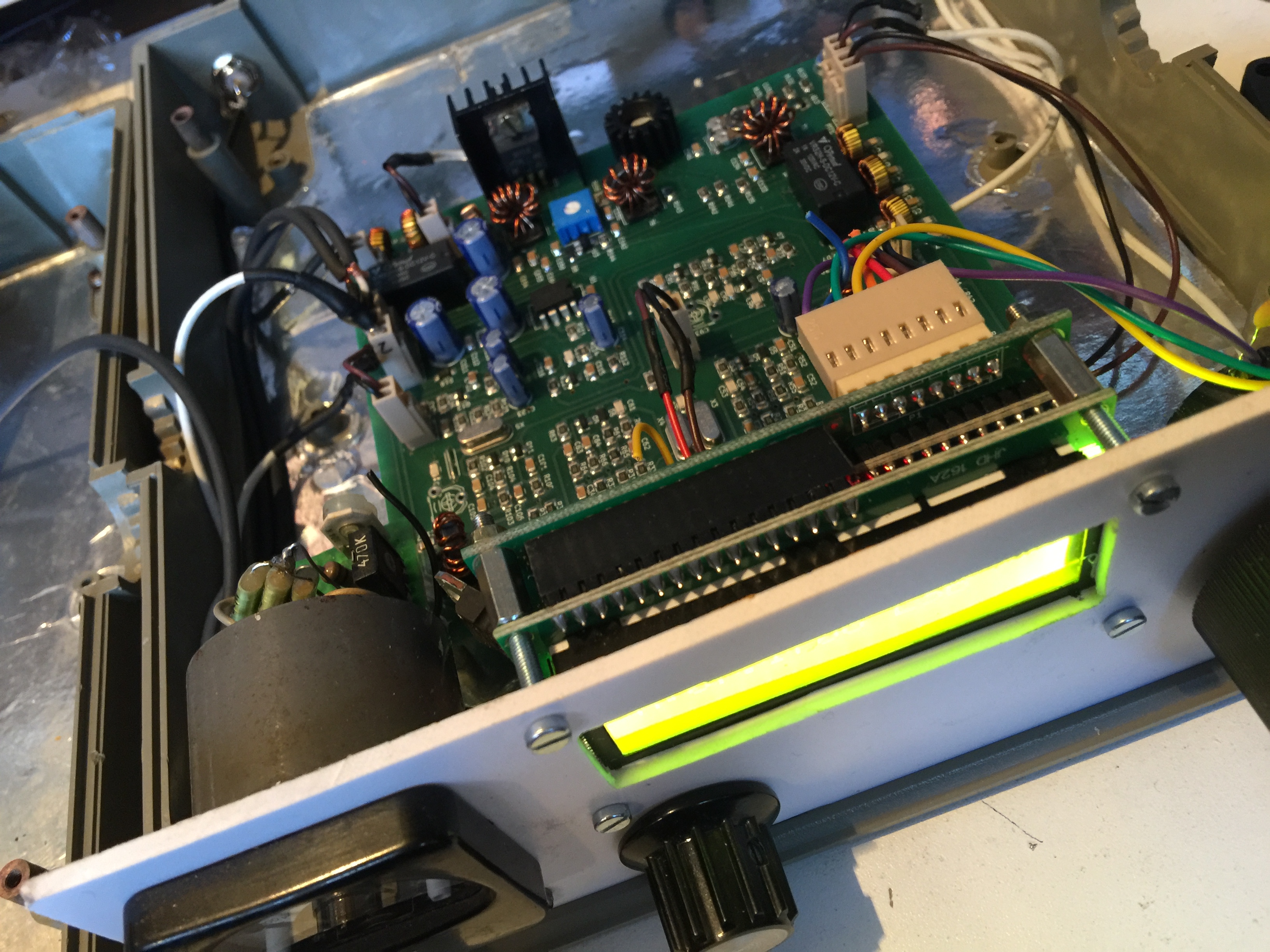
Now i am QRV with all these modifications…
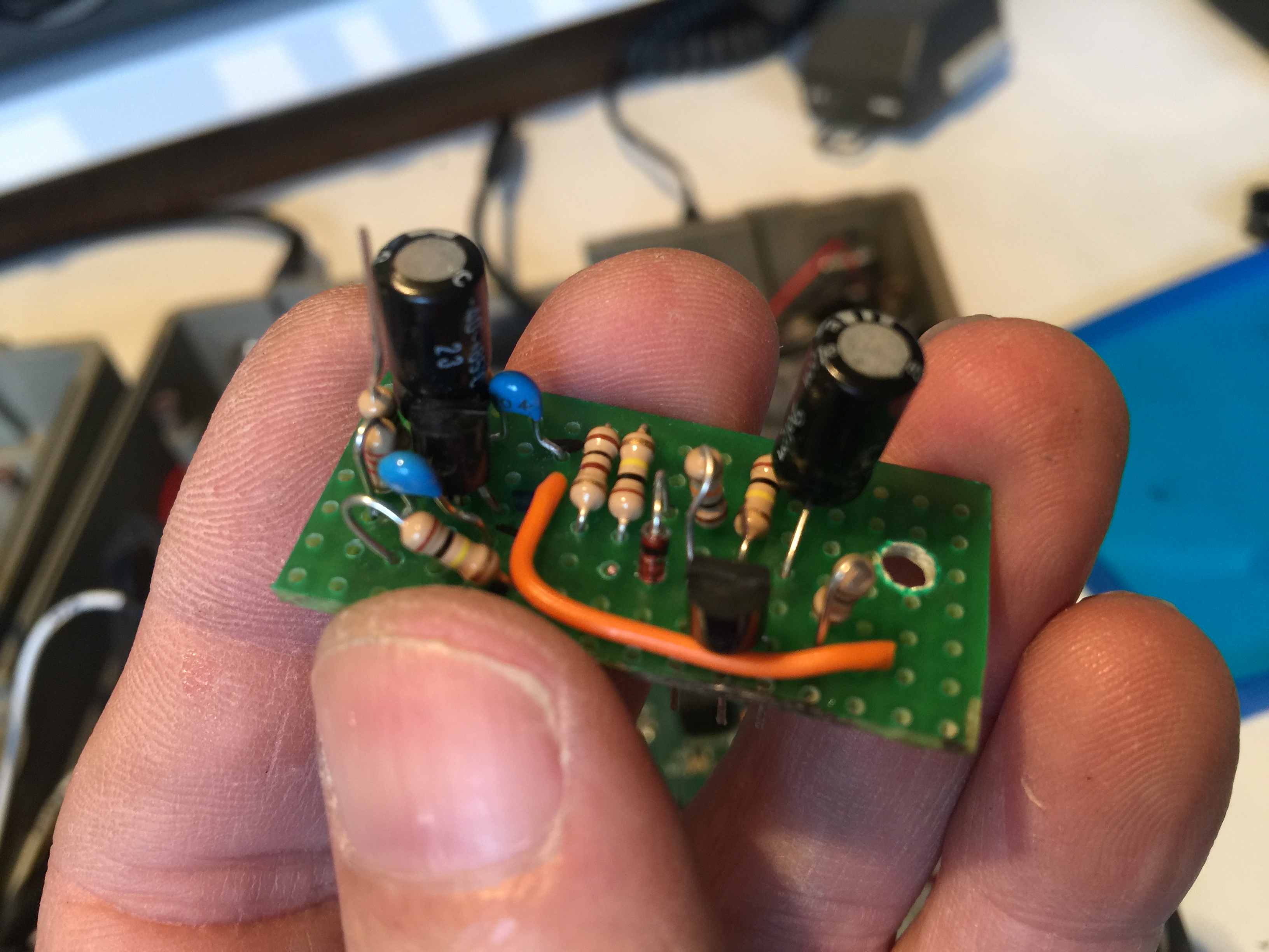
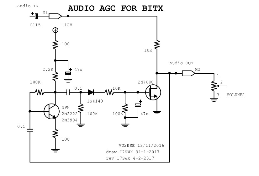
AGC
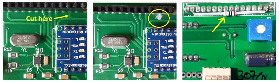
Adjust back light LCD
Backlight too strong on Ubitx40 ?
You can change the value of resistor as explained on the net but as it is CMS, and perhaps not so easy, you can just add a resistor of 390 ohms between pins 2 and 15 and cut pin 15 from P2….
On the Bitx40, 5v is directly connected from Raduino to LCD. Fortunatly the LCD has a 10 ohms resistor….
Some things to do…

QSO from UBITX to BITX40
F5NLG (10w) with F6HOY (3w) on 7.160Mhz on 20th of september