
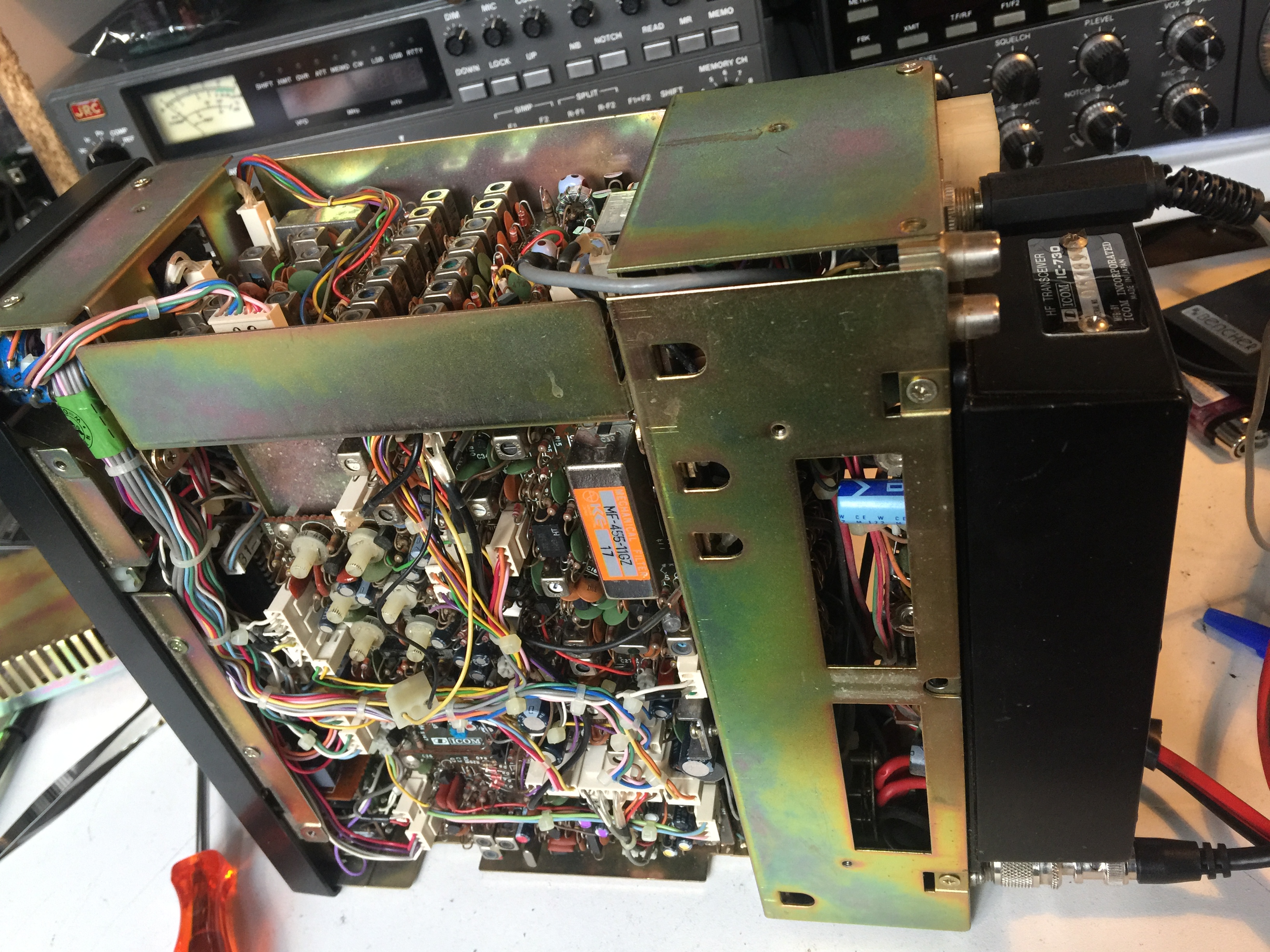
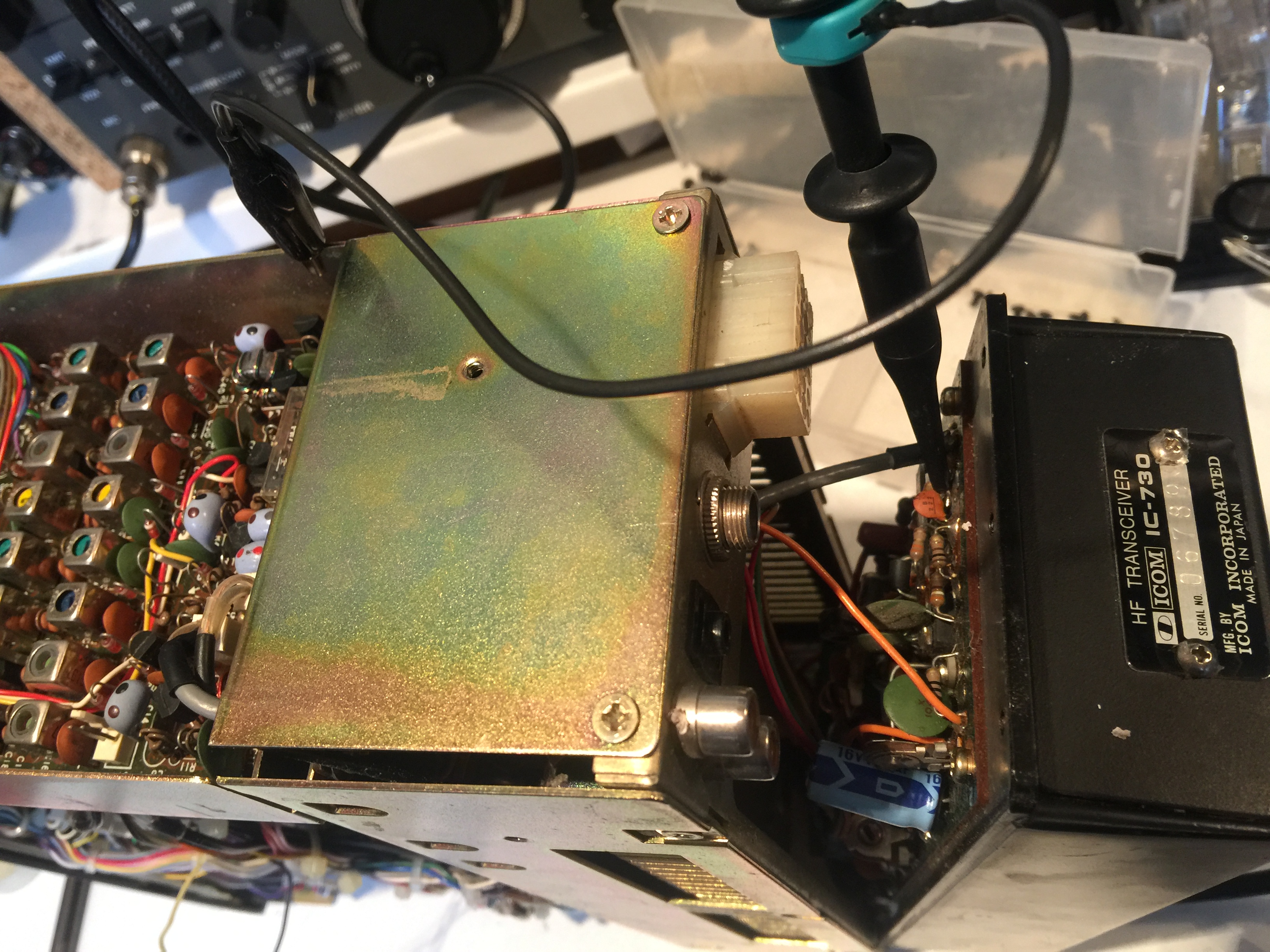
Icom IC730
My first modern transceiver as soon as i got my licence. I have done several contest with it in /P
Still at home but with a problem on PA: Just 5w due to a bad driver. I repaired several bad parts.

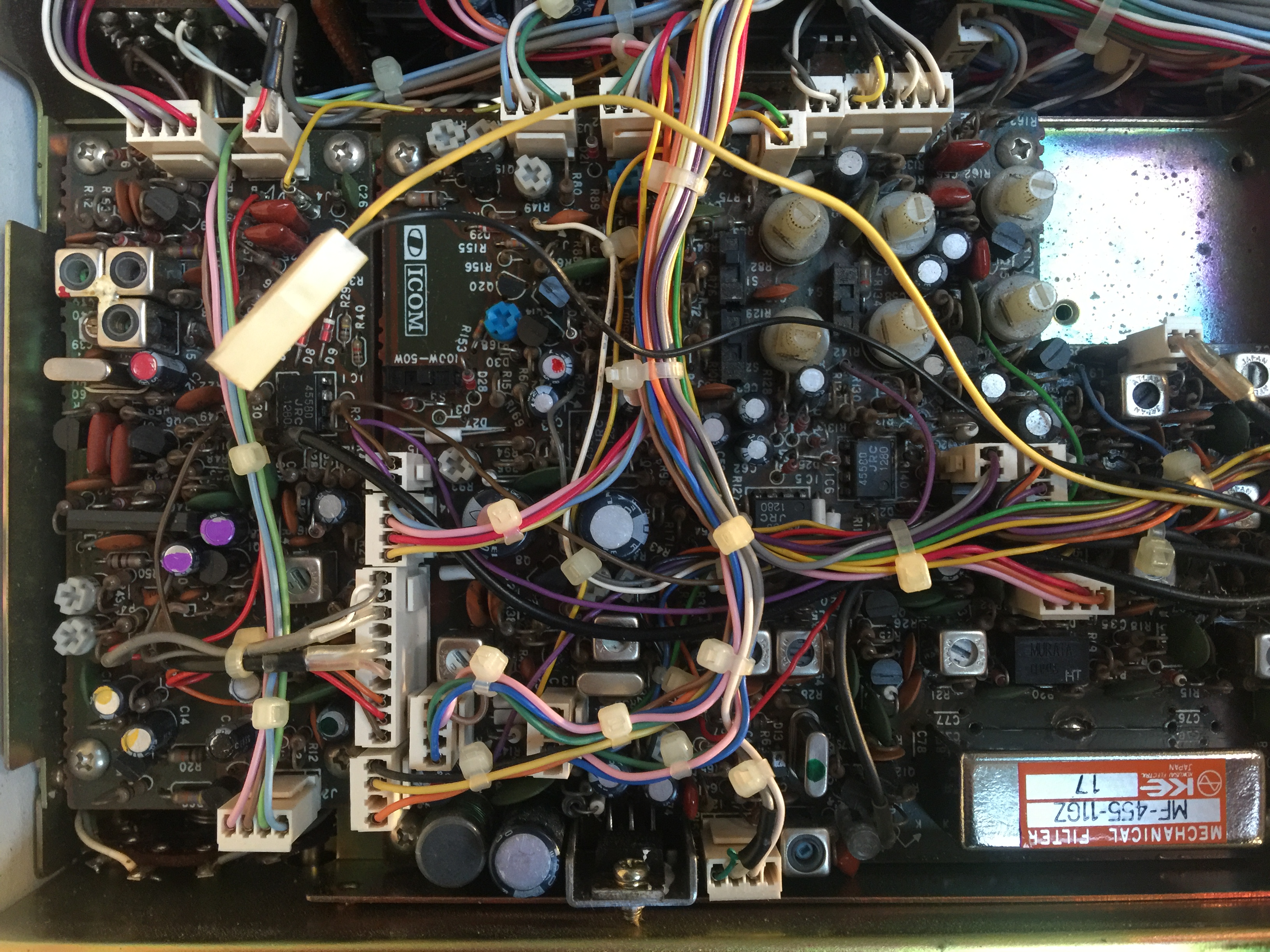
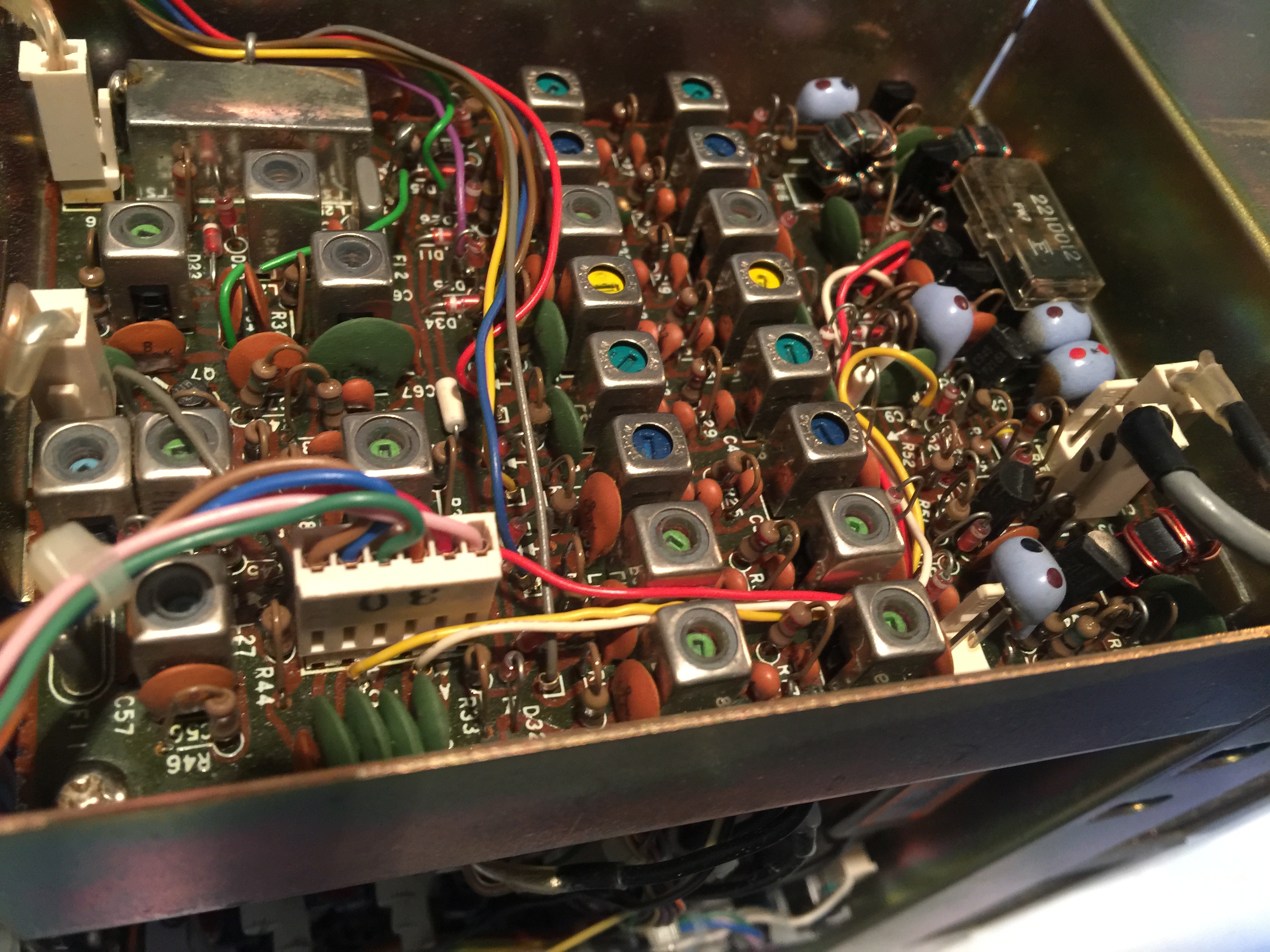
Though the IC-730 is a good-performing, reliable radio, many of these units have been in service for a number years and are beginning to show their age. The following preventative maintenance procedures should be done to all IC-730’s that are in need of repair.
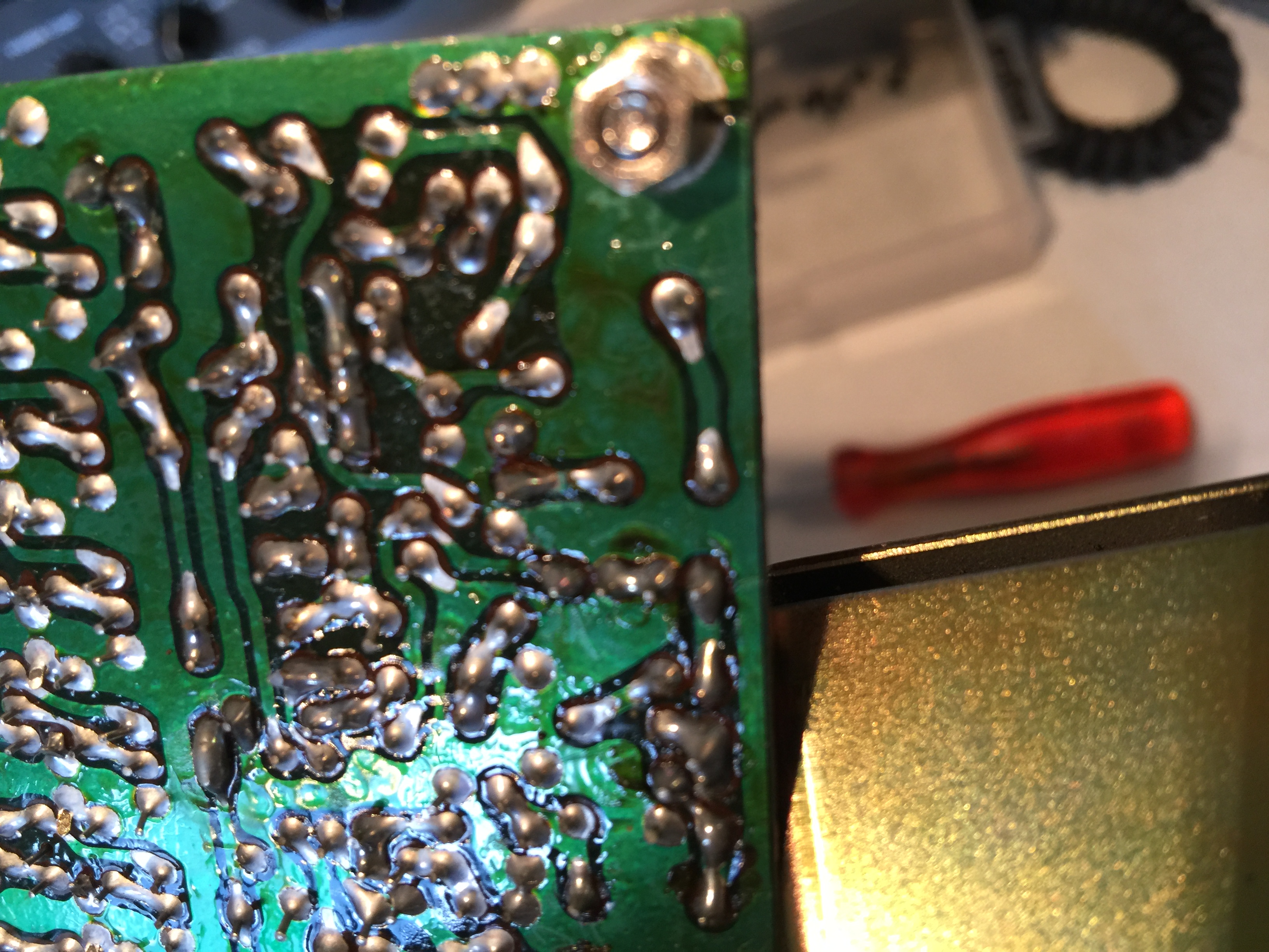
1.) On the RF unit, resolder the J2 and J3 connectors. Due to the relatively thick coax cables on the connectors, these solder joints tend to crack with age and cause intermittent transmit and receive problems.
________________________________________
2.) Make sure the receiver preamp works. If inoperative, replace relay RL1 on the RF unit. Install the factory update to prevent relay failure.
________________________________________
3.) Check transistor Q5 on the RF unit. If it is a 2SC945Q, replace it with the improved 2SC2878B to prevent spurious output from the transmitter and failure of the driver transistors. If Q5 is a type 1636, it doesn’t need to be replaced.
________________________________________
4.) Clean the RIT pot and switch with tuner cleaner. These controls are usually noisy and erratic, making the RIT hard to use.
________________________________________
5.) Tighten the chrome-plated PC board mounting screws. The screws and spacers tend to come loose if the radio is used in a high-vibration, mobile environment. Don’t forget to tighten the screws on the logic and IF units located beneath the main unit.
________________________________________
6.) Check the bandwidth coupler for proper tightness. Tighten as needed.
IC-730 Servicing
Symptom: No RX/TX at all. Display is OK.
Probable Cause: Open R1 resistor on reg. unit.
Cure: Replace R1 resistor (4.7 ohm, 1/2 watt).
________________________________________
Symptom: Preamp inoperative or intermittent. RX may be noisy.
Probable Causes: 1) Bad preamp RL1 relay on RF unit. 2) Cracked solder on RF unit in preamp section.
Cure: Replace bad relay RL1 (FBR221D012). Carefully examine the preamp section of the RF unit for bad joints and resolder as needed.
________________________________________
Symptom: Intermittent low RX sensitivity. Actuating PTT temporarily restores RX or causes it to drop out again.
Probable Cause: Intermittent preamp relay on RF unit, or intermittent T/R relay on filter unit.
Cure: Replace RL1 relay (FBR221D012) on RF unit. If this doesn’t help, replace RL1 relay (SR-202) on filter unit.
________________________________________
Symptom: Unit jumps frequency unexpectedly when turning VFO knob. Digital display does not track with this jump. The frequency jump is consistent and happens at the same place every time. Actual operating frequency does not match in some parts of the bands.
Probable Cause: LDO is out of alignment.
Cure: Adjust R22 trimmer pot on main unit for best performance.
________________________________________
Symptom: Frequency instability.
Probable Cause: Dirty RIT/XIT pot and switches.
Cure: Clean dirty RIT/XIT pots and switches with Blue Shower solvent.
________________________________________
Symptom: Drastic change in audio frequency response between USB and LSB., i.e. USB audio has too much bass while LSB audio has too much treble. TX frequency response is also poor.
Probable Cause: Misadjustment of the BFO or IF shift oscillator.
Cure: Realign BFO and IF shift oscillator as per page 8-4 and 8-5 of the service manual.
________________________________________
Symptom: Intermittent TX output.
Probable Cause: Cracked solder joints at J3 connector on RF unit.
Cure: Resolder solder joints at J3 connector.
________________________________________
Symptom: Distorted/raspy-sounding SSB TX. Carrier power present in SSB modes. Complaints of RFI. Unit tests fine on dummy load.
Probable Causes: 1.) Inadequate station ground. 2) External power supply used with unit needs additional RF decoupling.
Cure: Recheck station ground. Improve if necessary. If a 3rd party power supply is being used with radio, install additional decoupling capacitors across output terminals.
________________________________________
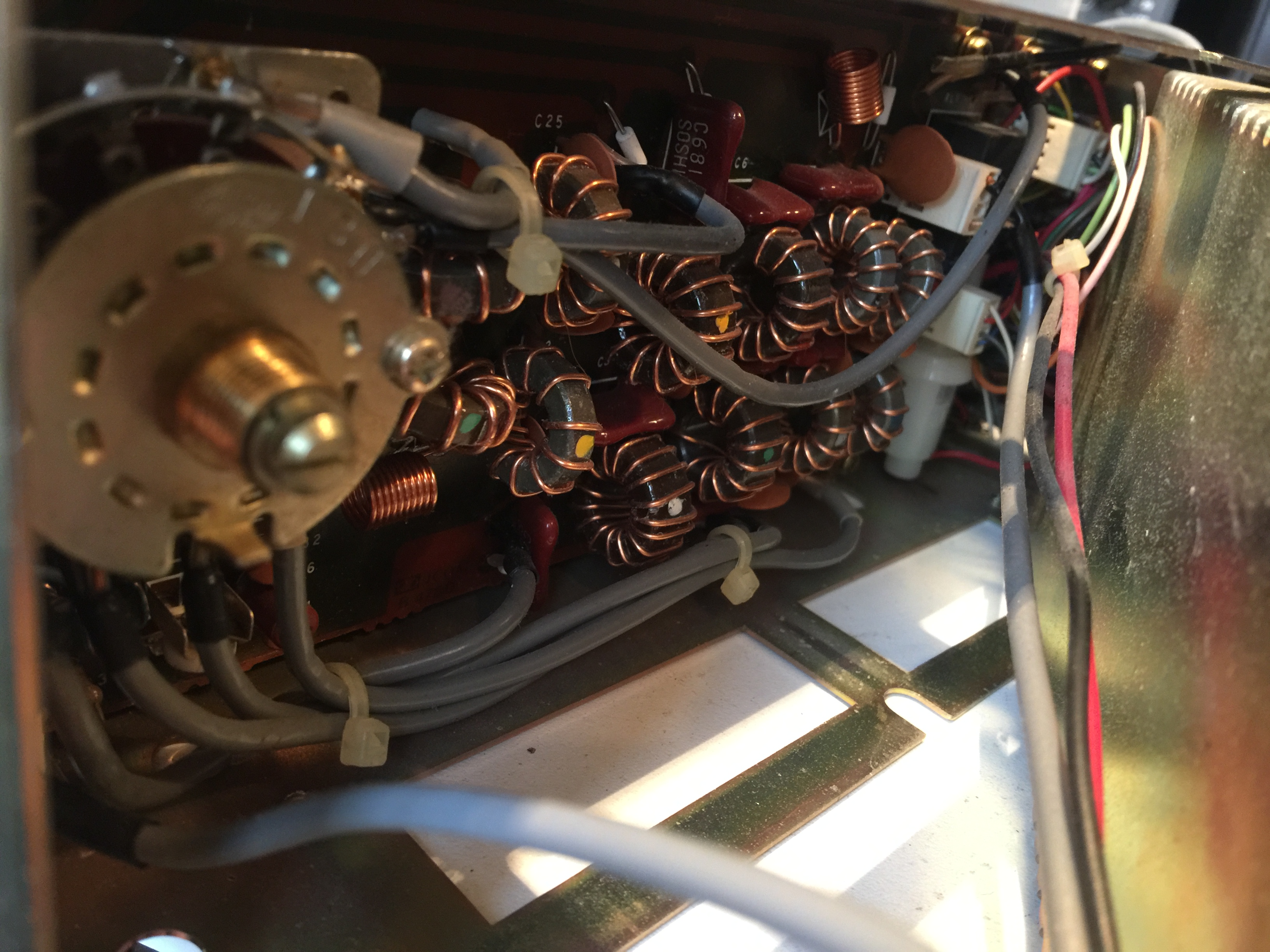
Symptom: TX oscillations, or low spurious output.
Probable Causes: 1) Bad Q5 transistor on RF unit. 2) Bad electrolytic capacitors on PA unit. 3) Band switch is misaligned. 4) Bad drivers or PA transistors.
Cure: Disconnect J2 connector on the RF unit and see if the problem goes away. If it does, then Q5 transistor is most likely bad (replace it with a 2SC2878B). If disconnecting J3 has no effect, examine the PA unit. Replace C18 and/or C23 capacitors if they appear swollen or overheated. Check alignment of the front and rear band switch wafers. If none of the above are causing the problem, then most likely the drivers or PA final transistors are bad.
Remarks: If Q5 transistor on the RF unit is a 2SC945, it should be replaced with a 2SC2878B.
Links and PDF:
IC-730_second_IF_filter_failure
IC-730_Murata_CFJ455K5_datasheet
Others nice infos on IC730: http://radioaficion.com/mods/ic-730-most-common-service/
Icom IC745
All new at home. I find it for 50€ in a hamfair.
I repair it. All is perfect and great transceiver.

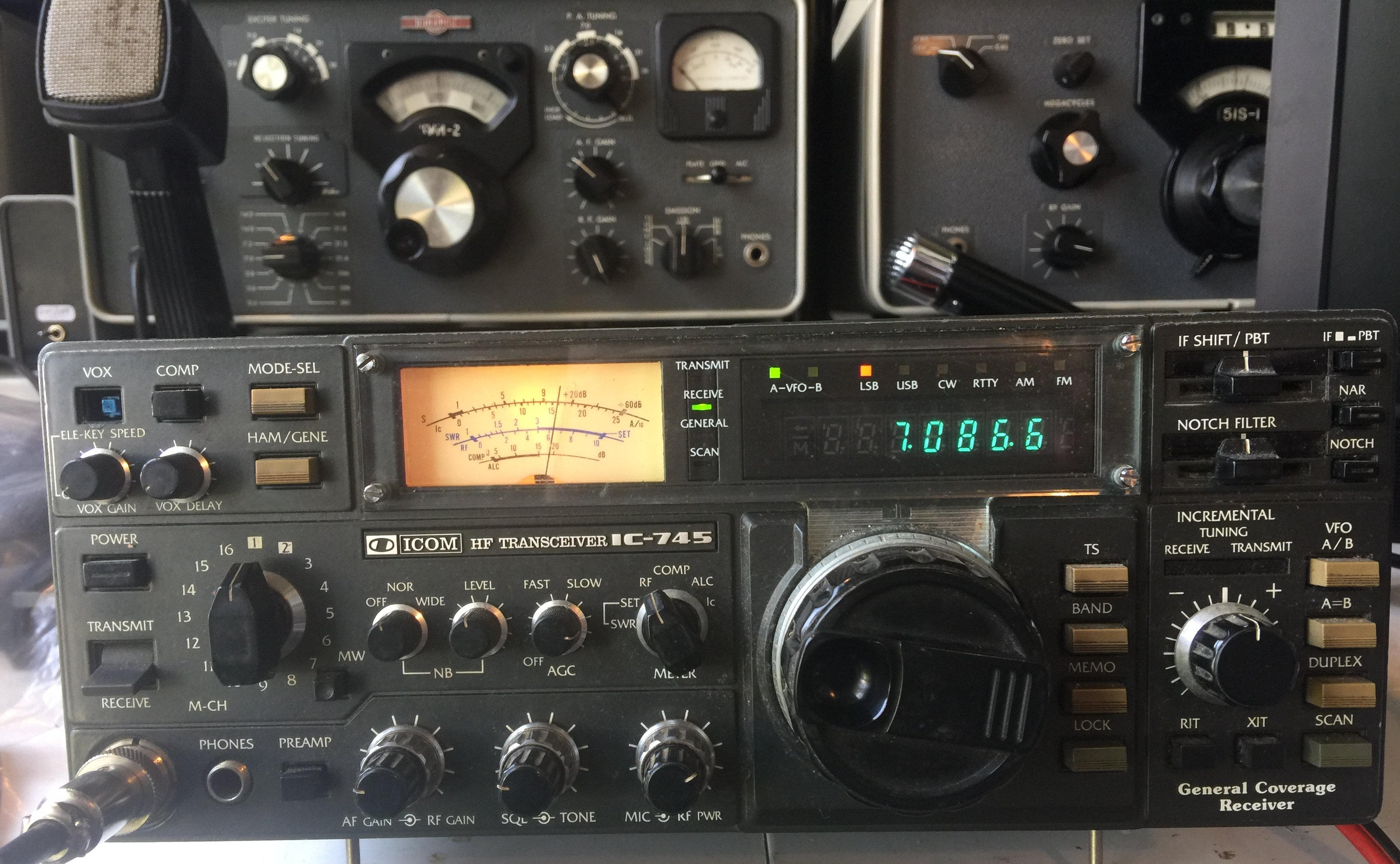

In the early 1980s Icom America marketed a group of transceivers and radios that utilized the latest state-of-the-art computer technology to enhance the operation of the radios. This technology improvement allowed hams to afford a reasonably priced high performance transceiver which until then was only available on units costing much more. Features now available to the hams included: higher frequency stability, better frequency resolution, digital frequency display, almost instant recall of saved frequencies (memory channels), quick mode signal processing and built in tones and offsets for the rapidly emerging repeater operation.
Implementation of all these features required a CPU with associated logic circuitry. In the early 80s, the most cost effective way to implement data processing and memory functions was through a DRAM (Dynamic Random Access Memory) to control the CPU. This DRAM was a volatile memory integrated circuit which required a lithium battery to retain its instruction set. The following receivers and transceivers had such RAM units: IC-271 ; IC-471 ; IC-1271 ; IC-745 ; IC-751/A ; IC-R71A
The lithium batteries in these units typically lasted about 5 to 7 years before replacement was required. This was specifically noted in each of the Owners Manuals for the products.
This lithium battery can be replaced by the radio owner if care is used. The following is a recommended procedure to accomplish this:
Procedure
- Disconnect the power cable from the radio, and take the cover off.
- Unplug the RAM board and remove it from the radio.
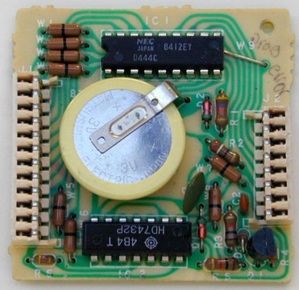
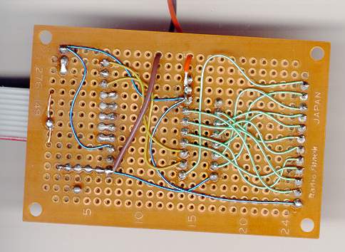
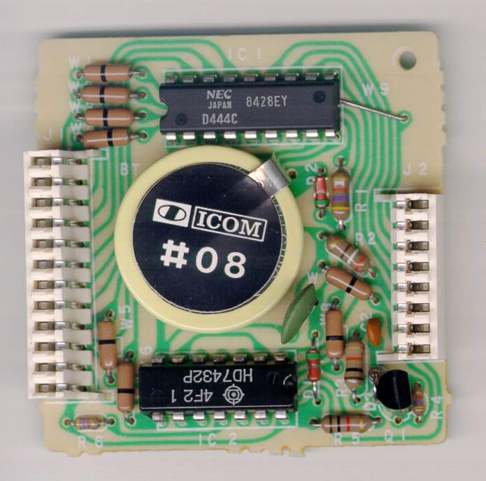
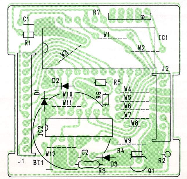
- Temporarily solder a 3 Volt DC battery source across the existing battery terminals (see suggested connection points on the circuit board pictures).
- Unsolder the old lithium battery and replace it with a new one. (BR2325 1HC, ICOM stock number 945 03112)
- Unsolder your temporary 3 Volt DC source.
- Reinstall the RAM board into the radio.
Cautions
- Do not use an AC powered 3 Volt DC source, your grounded soldering iron tip could short out the battery (+) terminal. Use a 3 Volt battery DC source only (2 alkaline cells for example).
- Do not solder the external DC wires directly to the lithium battery tab pads. If you do so, you will not be able unsolder the battery without having the wires drop off.
- If by accident you lose power to the RAM unit it must be sent to Icom America for reprogramming.
- Be careful not to damage or bend the connector pins on the radio side while removing or reinstalling the RAM card.
RAM card version A
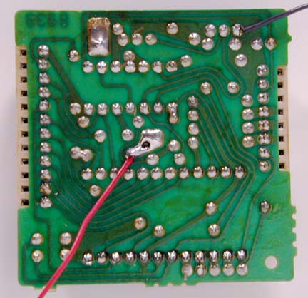
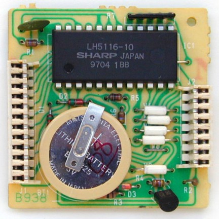
RAM card version B

Procedure to re-program the IC-751 or IC-745 RAM board
More infos on: http://gokarters.com/smf/index.php?topic=2766.0
 >>>> icom-pgm

 >>>>ICOMRAM
TWO solutions or approaches to the Icom EX-314 board problem:
-
Use a software and tools to reload the EPROM. But not very easy
- Purchase a modern replacement board — and no longer worry about the volatile RAM memory.
Exemple for a new one:
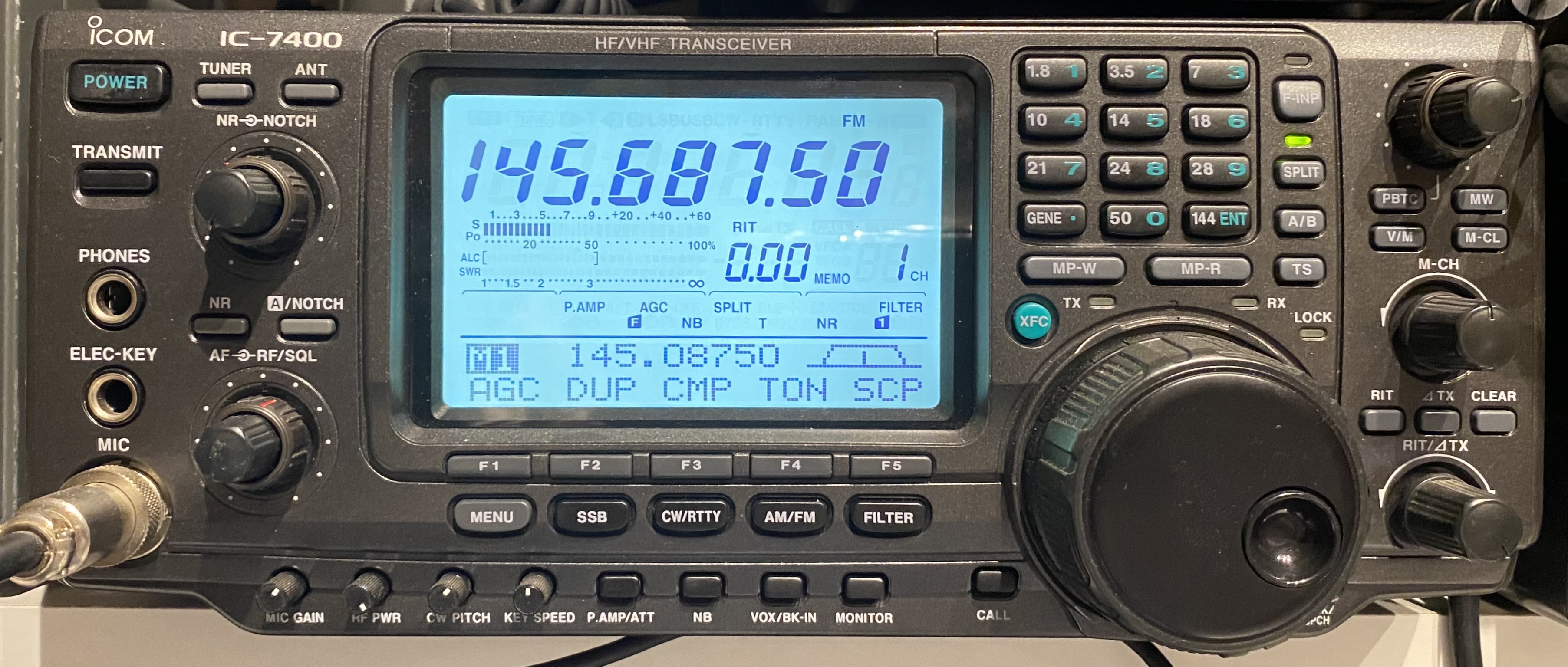
ICOM IC7400
A fine TX with VHF
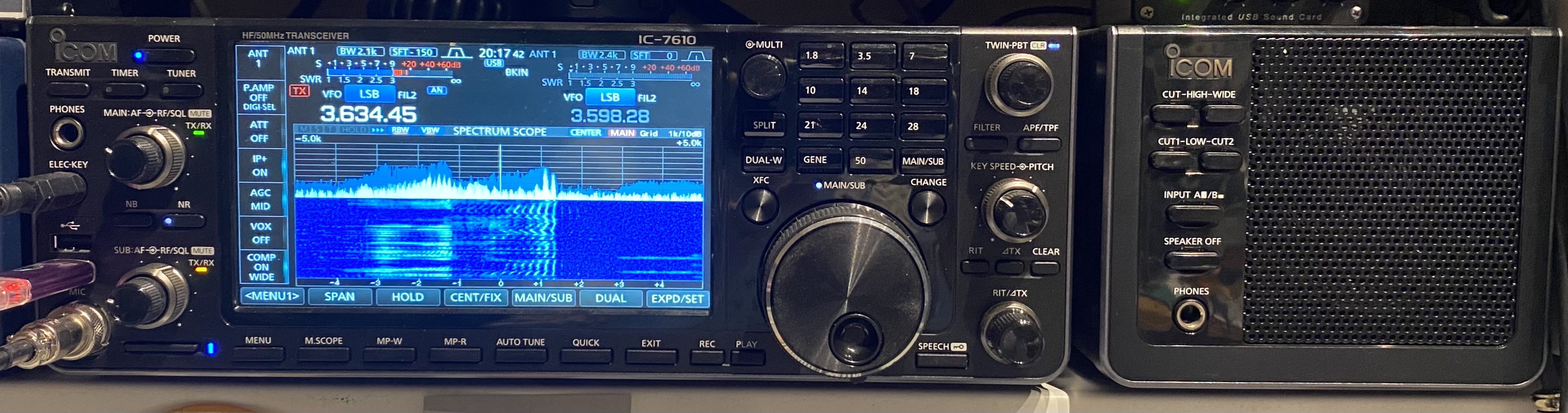
ICOM IC7610
My preference… I also use it in Remote with « RemoteTX.net »